:+86 15106109009
:sales@couplingzy.com

 vi
vi


Độ ổn định của khớp nối linh hoạt bằng kim loại trong môi trường nhiệt độ khắc nghiệt
Khớp nối đàn hồi kim loại chiếm một vị trí khác biệt trong truyền lực cơ học: không giống như các khớp nối linh hoạt dựa trên polymer có hiệu suất bị ràng buộc chặt chẽ với cửa sổ nhiệt hẹp, các khớp nối đàn hồi bằng kim loại có được sự tuân thủ từ sự biến dạng được kiểm soát của các phần tử kim loại - lò xo đĩa, lò xo lá, màng ngăn, ống thổi hoặc uốn cong ngoằn ngoèo. Cấu trúc hoàn toàn bằng kim loại này mang lại cho họ lợi thế cơ bản về nhiệt. Tuy nhiên, nhiệt độ cực cao đặt ra những yêu cầu phức tạp và thường cạnh tranh về tính chất vật liệu, độ ổn định kích thước, trạng thái mỏi và tình trạng bề mặt. Hiểu cách khớp nối đàn hồi kim loại đáp ứng những nhu cầu này là điều cần thiết đối với các kỹ sư chỉ định hệ thống truyền động trong ngành hàng không vũ trụ, xử lý đông lạnh, sản xuất thép, tua bin khí và bất kỳ ứng dụng nào trong đó điều kiện môi trường xung quanh khác biệt đáng kể so với đường cơ sở thiết kế ở nhiệt độ phòng tiêu chuẩn.
Điều gì xác định khớp nối đàn hồi kim loại
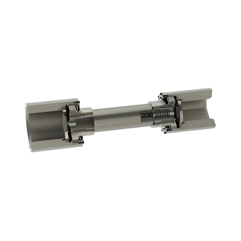
Khớp nối đàn hồi bằng kim loại truyền mô-men xoắn giữa trục dẫn động và trục dẫn động thông qua biến dạng đàn hồi của một hoặc nhiều phần tử kim loại dẻo thay vì thông qua tiếp xúc cơ học cứng hoặc tấm chèn polymer. Phần tử đàn hồi đồng thời thực hiện ba chức năng: nó mang mô-men xoắn truyền đi, nó điều chỉnh độ lệch trục tương đối thông qua độ uốn được kiểm soát và nó cung cấp một mức độ tuân thủ xoắn giúp lọc các dao động tốc độ và làm giảm tải trọng động.
Các họ khớp nối đàn hồi kim loại chính gặp phải trong thực tế công nghiệp và hàng không vũ trụ là:
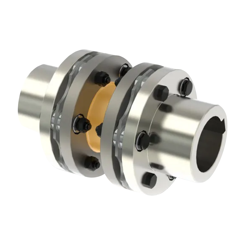
- Khớp nối dạng đĩa: Đĩa nhiều lớp hình tròn mỏng, thường bằng thép không gỉ hoặc hợp kim cứng kết tủa, được bắt vít xen kẽ vào mặt bích dẫn động và dẫn động. Sự uốn cong xảy ra trong gói đĩa vì nó điều chỉnh độ lệch góc và trục.
- Khớp nối màng: Một hoặc nhiều màng chắn hình khuyên có đường viền, thường bằng hợp kim titan hoặc thép hợp kim cao, có thể uốn cong để điều chỉnh độ lệch trong khi truyền mô-men xoắn cao với độ phản ứng rất thấp. Được sử dụng rộng rãi trong máy tuabin và tàu nén tốc độ cao.
- Khớp nối ống thổi: Một ống kim loại có thành mỏng, lượn sóng - thường là thép không gỉ austenit hoặc Inconel - cung cấp độ cứng xoắn để truyền mô-men xoắn trong khi uốn theo trục và ngang để bù cho độ lệch. Phổ biến trong các ứng dụng servo và bộ mã hóa chính xác.
- Khớp nối lá-lò xo (serpentine): Các dải kim loại hình sin hoặc ngoằn ngoèo xen kẽ giữa hai mặt bích trung tâm. Các dải lò xo uốn cong dưới tải trọng, mang lại khả năng điều chỉnh độ xoắn và độ lệch.
Tất cả các thiết kế này đều có chung đặc điểm xác định là hiệu suất của chúng phụ thuộc vào hoạt động cơ học của một phần tử đàn hồi kim loại - một yếu tố phụ thuộc khiến những thay đổi do nhiệt độ gây ra trong đặc tính vật liệu trở thành mối quan tâm chính trong các ứng dụng trong môi trường khắc nghiệt.
Hiệu ứng nhiệt lên các phần tử đàn hồi kim loại
Nhiệt độ ảnh hưởng đến hoạt động của khớp nối đàn hồi kim loại thông qua một số cơ chế tương tác và đồng thời. Hiểu từng cơ chế riêng lẻ là điều kiện tiên quyết để đánh giá độ ổn định chung của khớp nối trong phạm vi nhiệt rộng.
Những thay đổi về mô đun đàn hồi
Mô đun đàn hồi của kim loại - tỷ lệ ứng suất và biến dạng trong vùng đàn hồi tuyến tính - giảm khi nhiệt độ tăng và tăng khi nhiệt độ giảm. Đối với thép không gỉ austenit thường được sử dụng trong các khớp nối đĩa và ống thổi, mô đun đàn hồi ở 500°C thường là Thấp hơn 15–18% hơn ở nhiệt độ phòng, trong khi ở –200°C nó có thể cao hơn 10–12%. Sự thay đổi này ảnh hưởng trực tiếp đến độ cứng xoắn của khớp nối: bộ đĩa hoặc màng ngăn mang lại độ cứng góc xác định ở 20°C sẽ mềm hơn đáng kể ở nhiệt độ cao và cứng hơn khi làm lạnh.
Hậu quả thực tế là sự thay đổi tần số xoắn tự nhiên của hệ thống truyền động. Nếu hệ thống đã được điều chỉnh ở nhiệt độ phòng để đặt tần số cộng hưởng của nó cách xa tần số kích thích đang vận hành một cách an toàn, thì sự thay đổi mô đun đáng kể ở nhiệt độ sử dụng có thể khiến sự cộng hưởng đó gần hơn với tốc độ vận hành, gây ra những hậu quả có thể gây tổn hại. Do đó, việc hiệu chỉnh nhiệt của tính toán tần số riêng xoắn là bắt buộc đối với các hệ thống hoạt động tốt ngoài phạm vi nhiệt độ môi trường.
Giãn nở nhiệt và thay đổi kích thước
Các thành phần kim loại giãn nở khi nóng lên và co lại khi làm mát tỷ lệ với hệ số giãn nở nhiệt (CTE) của chúng và sự thay đổi nhiệt độ đã trải qua. Trong khớp nối đàn hồi bằng kim loại, điều này ảnh hưởng đến:
- Phù hợp với lỗ khoan và trục: Bộ phận chống nhiễu có kích thước ở nhiệt độ phòng có thể lỏng ra ở nhiệt độ cao nếu trục và trục giãn nở ở các tốc độ khác nhau — một mối lo ngại nghiêm trọng khi kết hợp các kim loại khác nhau, chẳng hạn như trục màng titan trên trục thép.
- Tải trước bu lông: Nếu phần tử linh hoạt và các bu lông kẹp nó làm bằng các vật liệu khác nhau với CTE khác nhau, chu trình nhiệt có thể làm thay đổi tải trước của bu lông, hoặc làm giảm lực kẹp (có nguy cơ trượt dưới mô-men xoắn) hoặc tăng lực đến mức gây căng thẳng cho mặt bích hoặc đĩa.
- Vị trí trục của máy được kết nối: Sự tăng trưởng nhiệt của trục dài và vỏ bọc tạo ra sự dịch chuyển dọc trục mà khớp nối phải đáp ứng. Khả năng dọc trục của phần tử linh hoạt phải được xác minh dựa trên sự tăng nhiệt thực tế trong toàn bộ phạm vi nhiệt độ vận hành.
Khi cụm khớp nối trải qua một dải nhiệt độ đáng kể - ví dụ: khớp nối nối trục tuabin nóng với hộp số làm mát - sự giãn nở nhiệt vi sai dọc theo trục khớp nối tạo ra tải trọng trục liên tục điều đó tác động lên tải trọng động từ việc truyền mô-men xoắn và bù sai lệch.
Sức mạnh năng suất và đặc tính mỏi
Tuổi thọ mỏi của phần tử đàn hồi kim loại bị chi phối bởi biên độ ứng suất tuần hoàn liên quan đến giới hạn độ bền của vật liệu. Cả giới hạn chảy và giới hạn độ bền mỏi của kim loại kết cấu đều phụ thuộc vào nhiệt độ:
- Tại nhiệt độ tăng cao , cường độ năng suất và giới hạn độ bền giảm. Bộ đĩa được thiết kế với giới hạn mỏi thoải mái ở nhiệt độ phòng có thể gặp ứng suất theo chu kỳ gần hoặc vượt quá giới hạn độ bền của vật liệu ở nhiệt độ vận hành dự kiến, làm giảm đáng kể tuổi thọ sử dụng.
- Tại nhiệt độ đông lạnh , hầu hết các loại thép hợp kim cao và hợp kim titan đều giữ lại hoặc cải thiện một chút độ bền kéo và độ bền chảy của chúng. Tuy nhiên, một số vật liệu - đặc biệt là thép cacbon và thép không gỉ ferit nhất định - trải qua quá trình chuyển đổi từ dẻo sang giòn dưới nhiệt độ tới hạn, sau đó vết nứt có thể xảy ra ở mức ứng suất thấp hơn nhiều so với giới hạn chảy danh nghĩa. Lựa chọn vật liệu có độ bền đông lạnh tốt (năng lượng va đập Charpy cao ở nhiệt độ làm việc tối thiểu) là yêu cầu thiết kế cơ bản cho các khớp nối trong dịch vụ ở nhiệt độ thấp.
Thư giãn và căng thẳng
Ở nhiệt độ trên khoảng 30–40% điểm nóng chảy tuyệt đối của kim loại (ngưỡng rão), ứng suất kéo dài sẽ gây ra biến dạng dẻo chậm, phụ thuộc vào thời gian được gọi là rão. Đối với thép, từ biến thực tế trở nên đáng kể ở nhiệt độ khoảng 400–450°C; đối với siêu hợp kim niken, ngưỡng này cao hơn đáng kể.
Trong khớp nối đàn hồi bằng kim loại hoạt động ở nhiệt độ cao, hiện tượng rão trong phần tử mềm hoặc trong các bu lông kẹp sẽ dẫn đến thư giãn căng thẳng - giảm dần ứng suất đàn hồi xuất hiện khi lắp ráp. Các mối nối bu lông có thể bị mất tải trước; gói đĩa có thể mất một bộ vĩnh viễn; màng ngăn có thể có độ lệch góc cố định. Kết quả là khớp nối không còn hoạt động như thiết kế, độ cứng bị thay đổi, tuổi thọ mỏi giảm và công suất mô-men xoắn có khả năng bị tổn hại. Đối với các ứng dụng trên ngưỡng rão của hợp kim tiêu chuẩn, vật liệu ghép phải được chọn từ các loại nhiệt độ cao có khả năng chống rão đã được chứng minh, chẳng hạn như Inconel hoặc Waspaloy được làm cứng kết tủa.
Quá trình oxy hóa và suy thoái bề mặt
Ở nhiệt độ cao trong môi trường oxy hóa, bề mặt của các nguyên tố đàn hồi kim loại có thể hình thành các vảy oxit. Đối với hầu hết các loại thép không gỉ và hợp kim niken, một lớp oxit bám dính bảo vệ được hình thành để hạn chế quá trình oxy hóa thêm. Tuy nhiên, chu kỳ nhiệt lặp đi lặp lại có thể khiến lớp này bị nứt, làm lộ ra kim loại mới và gây ra sự xuống cấp bề mặt ngày càng tăng. Rỗ bề mặt, hình thành cặn và quá trình oxy hóa giữa các hạt làm giảm mặt cắt ngang hiệu quả của các phần tử đĩa mỏng hoặc ống thổi và hoạt động như các vị trí tập trung ứng suất gây ra các vết nứt mỏi. Lớp phủ, xử lý bề mặt hoặc sử dụng hợp kim chống oxy hóa vốn có là các biện pháp bảo vệ quan trọng cho các khớp nối tiếp xúc với môi trường oxy hóa ở nhiệt độ cao.
Hành vi trong môi trường nhiệt độ cao
Các ứng dụng nhiệt độ cao cho khớp nối đàn hồi kim loại bao gồm bộ truyền động phụ kiện động cơ tuabin khí, khớp nối máy phát điện tua bin hơi nước, bộ truyền động chính của máy cán nóng, bộ truyền động băng tải lò công nghiệp và tàu máy nén hóa dầu. Trong những môi trường này, khớp nối có thể phải chịu nhiệt độ ổn định từ 250°C đến trên 600°C, với chu trình nhiệt chồng lên nhau trong quá trình khởi động và tắt máy.
Lựa chọn vật liệu cho dịch vụ nhiệt độ cao
Việc lựa chọn vật liệu phần tử linh hoạt là quyết định thiết kế quan trọng nhất đối với khớp nối nhiệt độ cao. Vật liệu được đánh giá theo một số tiêu chí:
- Thép không gỉ cứng do kết tủa (17-4 PH, 15-5 PH): Mang lại sự kết hợp tốt giữa độ bền, khả năng chịu nhiệt độ vừa phải (đến khoảng 300–350°C) và khả năng chống ăn mòn. Được sử dụng rộng rãi trong các khớp nối dạng đĩa cho các ứng dụng máy nén và máy bơm.
- Thép không gỉ Austenit (316L, 321, 347): Khả năng chống oxy hóa ở nhiệt độ cao tốt hơn so với các loại được làm cứng kết tủa, với cường độ sử dụng được ở khoảng 500–550°C. Các lớp ổn định 321 và 347 chống lại sự nhạy cảm và ăn mòn giữa các hạt sau khi tiếp xúc với nhiệt độ cao kéo dài.
- Siêu hợp kim gốc niken (Inconel 718, Waspaloy): Duy trì độ bền cao và khả năng chống rão ở nhiệt độ 650°C trở lên. Được sử dụng trong các khớp nối máy tuabin nhiệt độ cao đòi hỏi khắt khe nhất, nơi thép không gỉ tiêu chuẩn không đủ.
- Hợp kim titan (Ti-6Al-4V): Cung cấp cường độ riêng cao và khả năng chịu nhiệt độ cao tốt đến khoảng 300°C, kết hợp với mật độ thấp giúp giảm thiểu quán tính quay. Được áp dụng trong các khớp nối màng ngăn của máy tuabin và hàng không vũ trụ tốc độ cao trong đó trọng lượng là một hạn chế.
Cân nhắc bôi trơn ở nhiệt độ cao
Khớp nối đàn hồi kim loại are generally designed to operate without lubrication at the flexible element — the flexure is intended to be a clean elastic deformation, not a sliding contact. However, the hub bores, keyways, and fastener threads in high-temperature couplings require anti-seize compounds or high-temperature thread lubricants to prevent galling and to ensure that the coupling can be disassembled for inspection without damaging the mating surfaces. Standard molybdenum disulfide (MoS₂) paste is widely used up to approximately 450°C; copper-based anti-seize compounds extend protection to higher temperatures.
Chiến lược rào cản nhiệt và cách nhiệt
Khi khớp nối nối một máy rất nóng với một máy ở nhiệt độ môi trường xung quanh, sự dẫn nhiệt dọc theo trục và qua khớp nối có thể làm tăng nhiệt độ của các bộ phận phía sau lên trên giới hạn thiết kế của chúng. Các rào cản nhiệt - thường là một đoạn ngắn của hợp kim có độ dẫn điện thấp hoặc ống đệm phủ gốm - có thể được tích hợp trong miếng đệm khớp nối để hạn chế dòng nhiệt. Trong một số hệ thống lắp đặt, bộ phận bảo vệ khớp nối làm mát bằng không khí hoặc bằng nước cưỡng bức được sử dụng để duy trì khớp nối trong phạm vi nhiệt độ hoạt động của nó.
Hành vi trong môi trường đông lạnh
Các ứng dụng đông lạnh cho khớp nối đàn hồi kim loại bao gồm bộ truyền động máy nén khí tự nhiên lỏng (LNG), bộ truyền động bơm oxy lỏng và nitơ lỏng, hệ thống nam châm siêu dẫn, bộ truyền động bơm nhiên liệu hàng không vũ trụ và giàn thử nghiệm đường hầm gió đông lạnh. Nhiệt độ hoạt động trong các môi trường này dao động từ –50°C xuống –269°C (nhiệt độ heli lỏng).
Độ dẻo dai của vật liệu và sự chuyển đổi từ dẻo sang giòn
Mối quan tâm hàng đầu về vật liệu trong thiết kế khớp nối đông lạnh là độ bền khi gãy. Thép cacbon và thép không gỉ ferritic tiêu chuẩn trải qua quá trình chuyển đổi từ trạng thái dẻo sang giòn ở nhiệt độ thấp. Dưới nhiệt độ chuyển tiếp, những vật liệu này có thể bị hỏng đột ngột ở mức ứng suất thấp hơn nhiều so với giới hạn chảy danh nghĩa của chúng. Thép không gỉ Austenitic (304L, 316L) và hầu hết các hợp kim gốc niken không thể hiện quá trình chuyển đổi này — chúng vẫn bền và dẻo ở nhiệt độ heli lỏng, khiến chúng trở thành lựa chọn vật liệu tiêu chuẩn cho các bộ phận linh hoạt đông lạnh.
Hợp kim titan cũng giữ được độ dẻo dai thích hợp ở nhiệt độ đông lạnh, mặc dù chúng phải được đánh giá về độ giòn hydro trong các ứng dụng liên quan đến hydro lỏng.
Tăng độ cứng ở nhiệt độ thấp
Như đã lưu ý ở trên, mô đun đàn hồi của vật liệu kim loại tăng ở nhiệt độ đông lạnh. Khớp nối hộp xếp hoặc hộp đĩa được thiết kế để có độ cứng xoắn cụ thể ở nhiệt độ phòng sẽ cứng hơn đáng kể ở –196°C. Sự tăng độ cứng này làm thay đổi tần số xoắn tự nhiên của hệ thống truyền động lên trên và làm thay đổi sự phân bổ tải trọng động trong hệ thống. Phân tích xoắn của bộ truyền động phải được thực hiện ở cả điều kiện vận hành ấm và lạnh để xác nhận rằng không có cộng hưởng tới hạn nào được tạo ra trong toàn bộ phạm vi vận hành nhiệt.
Quản lý co nhiệt và vừa vặn
Các thành phần kim loại co lại ở nhiệt độ đông lạnh. Đối với lỗ trục được lắp vào trục bằng lực cản, sự co lại theo hướng làm tăng lực cản - điều kiện đông lạnh thường siết chặt các khớp nối trục hơn là nới lỏng chúng. Tuy nhiên, khi các kim loại khác nhau có hệ số giãn nở nhiệt khác nhau được kết hợp , sự co lại vi sai có thể tạo ra ứng suất tiếp xúc rất cao. Cần phải lựa chọn cẩn thận các kích thước vừa khít và kết hợp vật liệu, được xác minh bằng tính toán ứng suất nhiệt, để đảm bảo rằng không xảy ra hiện tượng lỏng lẻo hay biến dạng của mối lắp khít gây nhiễu trong phạm vi nhiệt độ vận hành.
Loại bỏ các yêu cầu bôi trơn
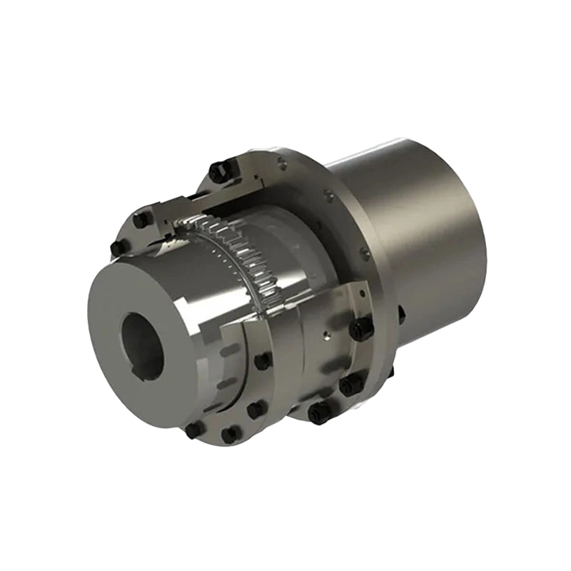
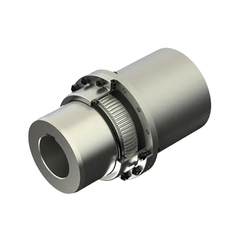
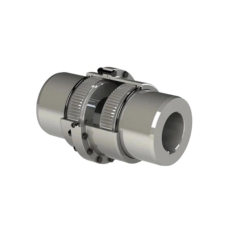
Một lợi thế vận hành đáng kể của khớp nối đàn hồi kim loại trong dịch vụ đông lạnh là khả năng tự do vốn có của chúng khỏi các yêu cầu bôi trơn ở phần tử linh hoạt. Các khớp nối được bôi trơn bằng mỡ thông thường - chẳng hạn như khớp nối bánh răng - không thể được sử dụng trong môi trường đông lạnh vì chất bôi trơn đông đặc ở nhiệt độ thấp, gây co giật. Do đó, khả năng uốn cong hoàn toàn bằng kim loại, không cần bôi trơn của các khớp nối đĩa, màng ngăn hoặc hộp xếp là điều cần thiết trong nhiều ứng dụng truyền động đông lạnh, ngoài việc là một lợi thế về hiệu suất.
Đạp xe nhiệt: Hiệu ứng tích lũy và tương tác mỏi
Nhiều ứng dụng ở nhiệt độ cực cao không liên quan đến hoạt động ở trạng thái ổn định được duy trì ở một nhiệt độ duy nhất - thay vào đó, khớp nối trải qua các chu kỳ nhiệt lặp đi lặp lại khi hệ thống khởi động từ trạng thái lạnh, đạt đến nhiệt độ vận hành và tắt lại. Mỗi chu trình nhiệt áp đặt một chu kỳ ứng suất nhiệt lên trạng thái ứng suất cơ học hiện có của phần tử linh hoạt.
Độ mỏi nhiệt - sự hình thành và lan truyền vết nứt do ứng suất nhiệt tuần hoàn - khác với độ mỏi cơ học nhưng có tương tác với nó. Tổng thiệt hại mỏi do phần tử dẻo tích lũy là tổng đóng góp từ các chu kỳ tải trọng cơ học (dao động mô-men xoắn, chu kỳ uốn do lệch trục) và chu kỳ ứng suất nhiệt. Trong các ứng dụng có chu trình nhiệt thường xuyên, sự đóng góp của mỏi nhiệt có thể tương đương hoặc lớn hơn sự đóng góp của mỏi cơ học. và cả hai đều phải được đưa vào đánh giá tuổi thọ sử dụng.
Chu kỳ nhiệt cũng thúc đẩy sự thay đổi kích thước lũy tiến thông qua việc ghép lại - sự tích tụ các mức biến dạng dẻo nhỏ theo từng chu kỳ - và thông qua sự giãn nở và co lại vi sai của các mối nối bu lông, có thể thay đổi tải trước theo thời gian. Do đó, việc định kỳ vặn lại các ốc vít và kiểm tra biến dạng vĩnh viễn của các bộ phận linh hoạt là các biện pháp bảo trì tiêu chuẩn cho các khớp nối trong dịch vụ tuần hoàn nhiệt.
Hiệu suất so sánh của các loại khớp nối đàn hồi kim loại trong dịch vụ nhiệt độ khắc nghiệt
Bảng dưới đây tóm tắt sự phù hợp của bốn loại khớp nối đàn hồi kim loại chính cho dịch vụ nhiệt độ cao và đông lạnh, cùng với các đặc tính hiệu suất chính liên quan đến nhiệt độ của chúng.
| Loại khớp nối | Vật liệu phần tử Flex điển hình | Giới hạn nhiệt độ cao (xấp xỉ) | Sự phù hợp đông lạnh | Bôi trơn tại Flex Element | Mối quan tâm về nhiệt độ cơ bản |
|---|---|---|---|---|---|
| Khớp nối gói đĩa | 17-4 PH SS, 316L SS, Inconel 718 | 300–600°C (phụ thuộc vào vật liệu) | Tốt (loại austenit) | Không cần thiết | Độ mỏi của đĩa ở giới hạn độ bền giảm; mất tải trước bu lông |
| Khớp nối màng | Ti-6Al-4V, 15-5 PH SS, Waspaloy | 300–650°C (phụ thuộc vào vật liệu) | Tốt (Hợp kim Ti, SS austenit) | Không cần thiết | Leo vào màng ngăn ở nhiệt độ cao; độ cứng tăng ở nhiệt độ thấp |
| Khớp nối ống thổi | 316L SS, Inconel 625 | 450–600°C | Tuyệt vời (SS austenit, Inconel) | Không cần thiết | Tường mỏng do quá trình oxy hóa; nồng độ ứng suất tuần hoàn tại các nếp gấp |
| Khớp nối lá-lò xo (Serpentine) | Thép lò xo, 17-7 PH SS | 250–350°C | Trung bình (kiểm tra sự chuyển tiếp giòn) | Không cần thiết | Lò xo đặt ở nhiệt độ cao; giảm tuổi thọ mệt mỏi |
Những cân nhắc về thiết kế cho hệ thống khớp nối nhiệt độ cực cao
Việc chỉ định khớp nối đàn hồi bằng kim loại để sử dụng trong môi trường khó khăn về nhiệt đòi hỏi một phương pháp kỹ thuật có cấu trúc vượt xa các tính toán sai lệch và mô-men xoắn ở nhiệt độ phòng tiêu chuẩn.
Phân tích xoắn được hiệu chỉnh theo nhiệt độ
Độ cứng xoắn của khớp nối và tần số xoắn tự nhiên của bộ truyền động hoàn chỉnh phải được tính toán ở nhiệt độ làm việc thực tế, có tính đến sự thay đổi mô đun của vật liệu phần tử dẻo. Nếu hệ thống truyền động vượt qua một phạm vi tốc độ trong quá trình khởi động trong khi khớp nối vẫn còn nguội thì tần số tự nhiên ở điều kiện lạnh cũng phải được kiểm tra để xác nhận rằng các cộng hưởng tới hạn không bị kích thích trong quá trình khởi động nhất thời.
Đánh giá tuổi thọ mỏi ở nhiệt độ sử dụng
Biên độ ứng suất tuần hoàn trong phần tử dẻo phải được đánh giá theo giới hạn độ bền của vật liệu ở nhiệt độ vận hành chứ không phải ở nhiệt độ phòng. Dữ liệu về độ mỏi đã được công bố đối với các vật liệu dự kiến ở nhiệt độ sử dụng dự kiến phải được lấy từ nhà cung cấp vật liệu hoặc từ các tài liệu tham khảo thiết kế đã được thiết lập. Hệ số an toàn mỏi ít nhất từ 1,5 đến 2,0 trên biên độ ứng suất, tham chiếu đến giới hạn độ bền nhiệt độ cao, là tiêu chí thiết kế được áp dụng phổ biến.
Tăng trưởng nhiệt và xác minh công suất trục
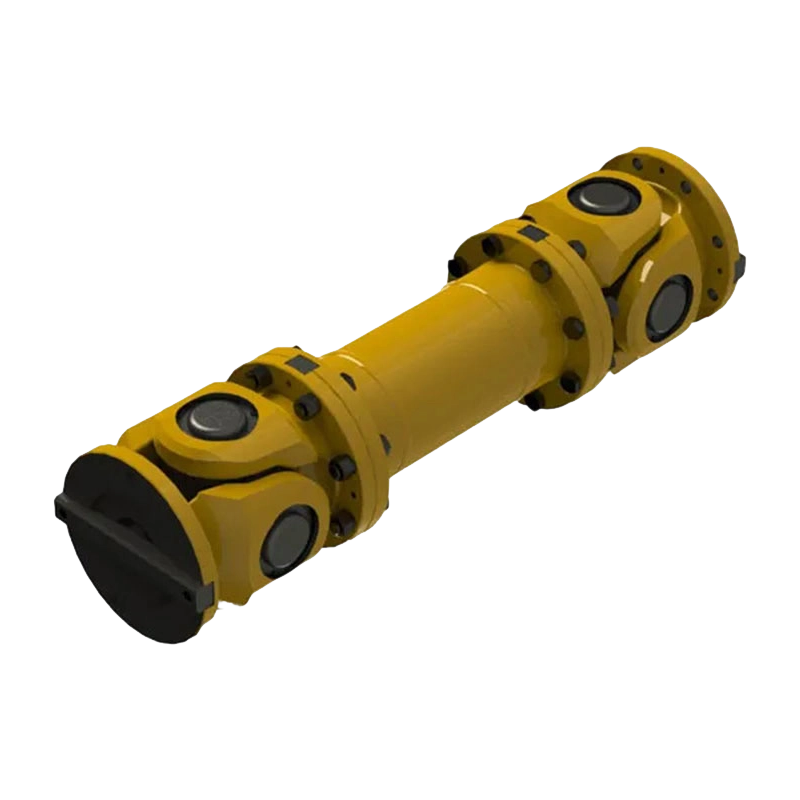
Tổng chuyển vị dọc trục mà khớp nối phải đáp ứng phải được tính toán từ sự tăng nhiệt của từng máy được kết nối trên toàn bộ phạm vi nhiệt độ hoạt động của nó. Khả năng chịu lực dọc trục của phần tử linh hoạt phải vượt quá chuyển vị tính toán này với một biên độ thích hợp. Khi tăng nhiệt lớn, khớp nối trục động (đoạn đệm) với hai phần tử linh hoạt - mỗi phần tử ở mỗi đầu - có thể cần thiết để phân phối nhu cầu trục và góc giữa hai mặt phẳng uốn.
Khả năng tương thích vật liệu và dây buộc
Tất cả các vật liệu trong cụm khớp nối - trục, phần tử linh hoạt, bu lông và bất kỳ bộ phận đệm nào - phải được đánh giá về khả năng tương thích trong môi trường nhiệt. Cần đặc biệt chú ý đến:
- Hệ số giãn nở nhiệt phù hợp giữa trục và phần tử linh hoạt để tránh sự tăng trưởng chênh lệch quá mức ở nhiệt độ vận hành.
- Lựa chọn vật liệu dây buộc để duy trì tải trước bu lông phù hợp trong phạm vi nhiệt; vật liệu bu lông hợp kim cao (A286, Inconel 718) được sử dụng trong các ứng dụng nhiệt độ cao để giảm thiểu tổn thất tải trước.
- Khả năng tương thích điện khi các kim loại khác nhau tiếp xúc với độ ẩm ở nhiệt độ trung gian.
Chiến lược kiểm tra và giám sát
Khớp nối đàn hồi kim loại in extreme thermal service should be subject to a defined inspection protocol. Key inspection activities include:
- Kiểm tra trực quan và kích thước của các bộ phận linh hoạt tại mỗi lần đại tu lớn để phát hiện các dấu hiệu biến dạng vĩnh viễn, nứt bề mặt, hư hỏng do oxy hóa hoặc ăn mòn.
- Kiểm tra không phá hủy (kiểm tra thẩm thấu thuốc nhuộm hoặc kiểm tra hạt từ tính đối với vật liệu kim loại màu; thẩm thấu huỳnh quang đối với kim loại màu) của các vùng phần tử linh hoạt chịu ứng suất cao, đặc biệt là các lỗ bu lông đĩa và chuyển tiếp lỗ màng ngăn.
- Kiểm tra tải trước của chốt bằng cách kiểm tra mô-men xoắn hoặc đo độ giãn dài của bu-lông sau chu kỳ nhiệt đầu tiên và sau đó theo các khoảng thời gian xác định.
- Giám sát dấu hiệu rung trong quá trình vận hành để phát hiện những thay đổi trong tần số xoắn tự nhiên có thể cho thấy độ cứng của khớp nối bị thay đổi do sự xuống cấp của vật liệu hoặc do biến dạng cố định.
Thực hành bảo trì cho các ứng dụng yêu cầu nhiệt
Tuổi thọ sử dụng của khớp nối đàn hồi kim loại trong môi trường nhiệt độ khắc nghiệt bị ảnh hưởng mạnh mẽ bởi chất lượng và tính nhất quán của chương trình bảo trì áp dụng cho khớp nối đó. Các thực hành sau đây được khuyến nghị như một phần của kế hoạch bảo trì có cấu trúc:
- Thiết lập nhật ký chu trình nhiệt: Ghi lại số chu kỳ nhiệt (khởi động và tắt máy) được tích lũy bởi mỗi khớp nối trong các ứng dụng có số chu kỳ cao chẳng hạn như các đơn vị đạt đỉnh tuabin khí. Sử dụng dữ liệu này để theo dõi mức tiêu hao mỏi tích lũy so với tuổi thọ thiết kế của phần tử mềm.
- Áp dụng các hợp chất chống kẹt cho tất cả các ốc vít: Sử dụng hợp chất được xếp hạng cho nhiệt độ sử dụng tối đa dự kiến. Áp dụng lại ở mỗi lần tháo rời để ngăn chặn hiện tượng lõm và đảm bảo rằng mối quan hệ mô-men xoắn-độ căng của dây buộc vẫn có thể dự đoán được.
- Xác minh căn chỉnh khớp nối ở nhiệt độ vận hành: Nếu có thể, hãy kiểm tra độ thẳng hàng của trục với máy ở nhiệt độ vận hành bình thường của nó, vì sự tăng nhiệt của vỏ và giá đỡ có thể gây ra độ lệch không xuất hiện trong điều kiện căn chỉnh nguội.
- Thay thế các yếu tố linh hoạt theo lịch trình dựa trên điều kiện hoặc giới hạn cuộc sống: Đối với các ứng dụng quan trọng về an toàn, hãy thiết lập thời gian ngừng sử dụng cho các bộ phận linh hoạt dựa trên số giờ vận hành tích lũy và chu kỳ nhiệt, đồng thời ngừng sử dụng chúng trước giới hạn đó bất kể điều kiện rõ ràng.
- Lưu trữ các phần tử linh hoạt thay thế một cách chính xác: Các gói đĩa, màng ngăn và cụm ống thổi phải được bảo quản ở điều kiện khô ráo, sạch sẽ, không bị hư hỏng cơ học. Ngay cả những vết xước hoặc vết lõm nhỏ trên bề mặt trên các phần tử mỏng dẻo cũng có thể đóng vai trò là vị trí bắt đầu mỏi và có thể là nguyên nhân bị loại bỏ trước khi lắp đặt.
- Liên kết nhanh
- About
- Products
- Our Service
- News & Events
- Contact
- Dòng sản phẩm
- Khớp nối linh hoạt với các bộ phận không đàn hồi
- Khớp nối linh hoạt với các bộ phận đàn hồi kim loại
- Khớp nối linh hoạt với các bộ phận đàn hồi phi kim loại
- Khớp nối an toàn
- Khớp nối cứng
- Liên hệ với chúng tôi
- Tel : +86 511 8572 3800 +86 511 8572 3900
- Mobile : +86 15106109009
- Email : sales@couplingzy.com
- Add:Số 1 Đại lộ Zhongye Yingbin, Phố Gaozi, Khu Phát triển Kinh tế Dantu, Thành phố Trấn Giang, Tỉnh Giang Tô, Trung Quốc.


